
As discussed before, I am continuing to mentor for the All Saints’ College Robotics club, even though both my sons are now at university. I am also the Rescue Advisor on the Robocup Junior West Australian Committee for 2017.
Having a hobby that allows me to play with Lego and write software that actually does something physical in the real world is awesome. I would recommend purchasing a Lego Mindstorms EV3 set for any boy or girl that wants to learn to code while having lots of fun.
This sixth article covers using the Mindsensors Multiplexer for NXT/EV3 Motors with the EV3 Basic extensions for Microsoft Small Basic.
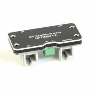
The Mindsensors Multiplexer for NXT/EV3 Motors is a Lego Mindstorms compatible device that allows two additional motors to be connected to a sensor port on the NXT or EV3 controller brick. Using a single Motor Multiplexer will allow a robot to have six motors rather than the usual limit of four, but you have to sacrifice a sensor port. This device does need an external battery to power the motors. I usually connect a 9V (transistor) battery to the green power connector.

Normally, the limit of four motors is sufficient, but if you require more, using this multiplexer can achieve what you need.
I have been experimenting with a robot using Mecanum wheels. These allow the robot to move in any direction and rotate depending on how much power is sent to each of the four wheels. The robot is using four EV3 Large Motors to drive the wheels and two EV3 Medium Motors to power other aspects of the robot. I have used the Motor Multiplexer to allow for the six motors.

Mindsensors provide the drivers (blocks) and samples to use the Motor Multiplexer with NXT-G and EV3-G and some other languages (RobotC and LeJOS), but do not have anything to show how it works with EV3 Basic.
Based on my experience with the EV3 Sensor Multiplexer, I was able to work through the documentation and create a suite of commands to allow controls of the two motors (M1 and M2).
As EV3 Basic does not have parameters or scoping of variables, the commands work by setting the appropriate variables and then calling the sub procedure. The commands are based on the functionality offered by the multiplexer, but do not include the Advanced PID control features. The example below assumes the Mindsensors Motor Multiplexer is connected to port 1 of the controller brick.
EV3 Basic
'  ** NXT MMX Test **

'  By David Musgrave

'  http://WinthropDC.com

'  Last Modified: 18-Jul-2017

' ** Setup Starts Here *******************************************************************************************************

' Initialise Variables
Finished = "False"
Clicks = ""

' Mindsensors.com NXT/EV3 Motor Multiplexer
I2CMotPort = 1
I2CMotAddr = 3
I2CMotReg = 0
I2CMotWriteByte = 0
I2CMotWriteData = Vector.Init(2, 0)
I2CMotReadByte = 0
I2CMotReadData = Vector.Init(2, 0)

M1Rotations = 0
M2Rotations = 0
MVoltage = 0
MCommand = 0
M1Rotate = 0
M2Rotate = 0
M1Speed = 0
M2Speed = 0
M1Seconds = 1
M2Seconds = 1
M1Brake = 1 '  1 = Brake, 0 = Float
M2Brake = 1 '  1 = Brake, 0 = Float
M1Ramp = 0 ' 1 = Ramp, 0 = No Ramp
M2Ramp = 0 ' 1 = Ramp, 0 = No Ramp
M1Wait = 0 ' 1 = Wait For Completion
M2Wait = 0 ' 1 = Wait For Completion
M1Status = 0
M2Status = 0
M1StatusBits = Vector.Init(8, 0)
M2StatusBits = Vector.Init(8, 0)
M1StatusString = "SRPCBOTL"
M2StatusString = "SRPCBOTL"

MRotate = 0
MStatus = 0
bits = 0

' ** Subroutines Starts Here *******************************************************************************************************

Sub MVRead
  I2CMotReg = 65 ' 0x41 Battery Voltage
  I2CMotWriteByte = 1 + 0
  I2CMotWriteData = Vector.Init(I2CMotWriteByte, I2CMotReg)
  I2CMotReadByte = 1
  I2CMotReadData = Vector.Init(I2CMotReadByte, 0)

  I2CMotReadData = Sensor.CommunicateI2C(I2CMotPort, I2CMotAddr, I2CMotWriteByte, I2CMotReadByte, I2CMotWriteData)
  MVoltage = I2CMotReadData[0] * 37 '  In milli Volts
EndSub

Sub M1Read
  I2CMotReg = 98 ' 0x62 Encoder position of Motor 1
  I2CMotWriteByte = 1 + 0
  I2CMotWriteData = Vector.Init(I2CMotWriteByte, I2CMotReg)
  I2CMotReadByte = 4
  I2CMotReadData = Vector.Init(I2CMotReadByte, 0)

  I2CMotReadData = Sensor.CommunicateI2C(I2CMotPort, I2CMotAddr, I2CMotWriteByte, I2CMotReadByte, I2CMotWriteData)
  If I2CMotReadData[3] >= 128 Then
    M1Rotations = - ((255-I2CMotReadData[3])*16777216 + (255-I2CMotReadData[2])*65536 + (255-I2CMotReadData[1])*256 + (255-I2CMotReadData[0]))
  Else
    M1Rotations = (I2CMotReadData[3]*16777216 + I2CMotReadData[2]*65536 + I2CMotReadData[1]*256 + I2CMotReadData[0])
  EndIf
EndSub

Sub M2Read
  I2CMotReg = 102 ' 0x66 Encoder position of Motor 2
  I2CMotWriteByte = 1 + 0
  I2CMotWriteData = Vector.Init(I2CMotWriteByte, I2CMotReg)
  I2CMotReadByte = 4
  I2CMotReadData = Vector.Init(I2CMotReadByte, 0)

  I2CMotReadData = Sensor.CommunicateI2C(I2CMotPort, I2CMotAddr, I2CMotWriteByte, I2CMotReadByte, I2CMotWriteData)
  If I2CMotReadData[3] >= 128 Then
    M2Rotations = - ((255-I2CMotReadData[3])*16777216 + (255-I2CMotReadData[2])*65536 + (255-I2CMotReadData[1])*256 + (255-I2CMotReadData[0]))
  Else
    M2Rotations = (I2CMotReadData[3]*16777216 + I2CMotReadData[2]*65536 + I2CMotReadData[1]*256 + I2CMotReadData[0])
  EndIf
EndSub

Sub M1ReadStatus
  I2CMotReg = 114 ' 0x72 Status Motor 1
  I2CMotWriteByte = 1 + 0
  I2CMotWriteData = Vector.Init(I2CMotWriteByte, I2CMotReg)
  I2CMotReadByte = 1
  I2CMotReadData = Vector.Init(I2CMotReadByte, 0)

  I2CMotReadData = Sensor.CommunicateI2C(I2CMotPort, I2CMotAddr, I2CMotWriteByte, I2CMotReadByte, I2CMotWriteData)
  M1Status = I2CMotReadData[0]
  ' Bit 0 = S - Speed Control is On
  ' Bit 1 = R - Motor is Ramping
  ' Bit 2 = P - Motor is powered
  ' Bit 3 = C - Positional Control is On
  ' Bit 4 = B - Motor is in Brake mode
  ' Bit 5 = O - Motor is overloaded
  ' Bit 6 = T - Motor is in timed mode
  ' Bit 7 = L - Motor is stalled
  M1StatusString = ""
  MStatus = M1Status
  For bits = 0 To 7
    If Math.Remainder(MStatus, 2) = 0 Then
      M1StatusBits[bits] = 0
      M1StatusString = M1StatusString + " "
    Else
      M1StatusBits[bits] = 1
      M1StatusString = M1StatusString + Text.GetSubText("SRPCBOTL", bits + 1, 1)
    EndIf
    MStatus = Math.Floor(MStatus / 2)
  EndFor
EndSub

Sub M2ReadStatus
  I2CMotReg = 115 ' 0x73 Status Motor 2
  I2CMotWriteByte = 1 + 0
  I2CMotWriteData = Vector.Init(I2CMotWriteByte, I2CMotReg)
  I2CMotReadByte = 1
  I2CMotReadData = Vector.Init(I2CMotReadByte, 0)

  I2CMotReadData = Sensor.CommunicateI2C(I2CMotPort, I2CMotAddr, I2CMotWriteByte, I2CMotReadByte, I2CMotWriteData)
  M2Status = I2CMotReadData[0]
  ' Bit 0 = S - Speed Control is On
  ' Bit 1 = R - Motor is Ramping
  ' Bit 2 = P - Motor is powered
  ' Bit 3 = C - Positional Control is On
  ' Bit 4 = B - Motor is in Brake mode
  ' Bit 5 = O - Motor is overloaded
  ' Bit 6 = T - Motor is in timed mode
  ' Bit 7 = L - Motor is stalled
  M2StatusString = ""
  MStatus = M2Status
  For bits = 0 To 7
    If Math.Remainder(MStatus, 2) = 0 Then
      M1StatusBits[bits] = 0
      M2StatusString = M2StatusString + " "
    Else
      M1StatusBits[bits] = 1
      M2StatusString = M2StatusString + Text.GetSubText("SRPCBOTL", bits + 1, 1)
    EndIf
    MStatus = Math.Floor(MStatus / 2)
  EndFor
EndSub

Sub MWriteCommand
  I2CMotReg = 65 ' 0x41 Write Command
  I2CMotWriteByte = 1 + 1
  I2CMotWriteData = Vector.Init(I2CMotWriteByte, I2CMotReg)
  I2CMotWriteData[1] = MCommand
  I2CMotReadByte = 1
  I2CMotReadData = Vector.Init(I2CMotReadByte, 0)

  I2CMotReadData = Sensor.CommunicateI2C(I2CMotPort, I2CMotAddr, I2CMotWriteByte, I2CMotReadByte, I2CMotWriteData)
EndSub

Sub M1Start
  I2CMotReg = 66 ' 0x42 Write Parameters of Motor 1
  I2CMotWriteByte = 1 + 8
  I2CMotWriteData = Vector.Init(I2CMotWriteByte, I2CMotReg)
  MRotate = M1Rotate
  If MRotate > 0 then
    I2CMotWriteData[4] = Math.Floor(MRotate/16777216)
    MRotate = MRotate - Math.Floor(MRotate/16777216)
    I2CMotWriteData[3] = Math.Floor(MRotate/65536)
    MRotate = MRotate - Math.Floor(MRotate/65536)
    I2CMotWriteData[2] = Math.Floor(MRotate/256)
    MRotate = MRotate - Math.Floor(MRotate/256)
    I2CMotWriteData[1] = MRotate
  Else
    MRotate = -MRotate
    I2CMotWriteData[4] = 255-Math.Floor(MRotate/16777216)
    MRotate = MRotate - Math.Floor(MRotate/16777216)
    I2CMotWriteData[3] = 255-Math.Floor(MRotate/65536)
    MRotate = MRotate - Math.Floor(MRotate/65536)
    I2CMotWriteData[2] = 255-Math.Floor(MRotate/256)
    MRotate = MRotate - Math.Floor(MRotate/256)
    I2CMotWriteData[1] = 255-MRotate
  EndIf
  I2CMotWriteData[5] = M1Speed
  I2CMotWriteData[6] = M1Seconds
  I2CMotWriteData[7] = 0 ' Command Register B
  I2CMotWriteData[8] = 0 ' Command Register A
  I2CMotWriteData[8] = I2CMotWriteData[8] + 1 * 1 ' Speed Control of your Motor
  I2CMotWriteData[8] = I2CMotWriteData[8] + 2 * M1Ramp ' Ramp the speed up or down
  I2CMotWriteData[8] = I2CMotWriteData[8] + 4 * 1 ' Relative change based on encoder values
  If M1Rotate <> 0 Then
    I2CMotWriteData[8] = I2CMotWriteData[8] + 8 * 1 ' Encoder control of your motor
  EndIf
  I2CMotWriteData[8] = I2CMotWriteData[8] + 16 * M1Brake ' Brake or Float at the completion of motor movement
  I2CMotWriteData[8] = I2CMotWriteData[8] + 32 * 1 - M1Brake ' Encoder active feedback
  If M1Seconds > 0 Then
    I2CMotWriteData[8] = I2CMotWriteData[8] + 64 * 1 ' Timed control of your motor
  EndIf
  I2CMotWriteData[8] = I2CMotWriteData[8] + 128 * 1 ' Go
  I2CMotReadByte = 1
  I2CMotReadData = Vector.Init(I2CMotReadByte, 0)

  I2CMotReadData = Sensor.CommunicateI2C(I2CMotPort, I2CMotAddr, I2CMotWriteByte, I2CMotReadByte, I2CMotWriteData)
  If M1Wait > 0 Then
    M1Wait()
  EndIf
EndSub

Sub M2Start
  I2CMotReg = 74 ' 0x4A Write Parameters of Motor 2
  I2CMotWriteByte = 1 + 8
  I2CMotWriteData = Vector.Init(I2CMotWriteByte, I2CMotReg)
  MRotate = M2Rotate
  If MRotate > 0 then
    I2CMotWriteData[4] = Math.Floor(MRotate/16777216)
    MRotate = MRotate - Math.Floor(MRotate/16777216)
    I2CMotWriteData[3] = Math.Floor(MRotate/65536)
    MRotate = MRotate - Math.Floor(MRotate/65536)
    I2CMotWriteData[2] = Math.Floor(MRotate/256)
    MRotate = MRotate - Math.Floor(MRotate/256)
    I2CMotWriteData[1] = MRotate
  Else
    MRotate = -MRotate
    I2CMotWriteData[4] = 255-Math.Floor(MRotate/16777216)
    MRotate = MRotate - Math.Floor(MRotate/16777216)
    I2CMotWriteData[3] = 255-Math.Floor(MRotate/65536)
    MRotate = MRotate - Math.Floor(MRotate/65536)
    I2CMotWriteData[2] = 255-Math.Floor(MRotate/256)
    MRotate = MRotate - Math.Floor(MRotate/256)
    I2CMotWriteData[1] = 255-MRotate
  EndIf
  I2CMotWriteData[5] = M2Speed
  I2CMotWriteData[6] = M2Seconds
  I2CMotWriteData[7] = 0 ' Command Register B
  I2CMotWriteData[8] = 0 ' Command Register A
  I2CMotWriteData[8] = I2CMotWriteData[8] + 1 * 1 ' Speed Control of your Motor
  I2CMotWriteData[8] = I2CMotWriteData[8] + 2 * M2Ramp ' Ramp the speed up or down
  I2CMotWriteData[8] = I2CMotWriteData[8] + 4 * 1 ' Relative change based on encoder values
  If M2Rotate <> 0 Then
    I2CMotWriteData[8] = I2CMotWriteData[8] + 8 * 1 ' Encoder control of your motor
  EndIf
  I2CMotWriteData[8] = I2CMotWriteData[8] + 16 * M2Brake ' Brake or Float at the completion of motor movement
  I2CMotWriteData[8] = I2CMotWriteData[8] + 32 * 1 - M2Brake ' Encoder active feedback
  If M2Seconds > 0 Then
    I2CMotWriteData[8] = I2CMotWriteData[8] + 64 * 1 ' Timed control of your motor
  EndIf
  I2CMotWriteData[8] = I2CMotWriteData[8] + 128 * 1 ' Go
  I2CMotReadByte = 1
  I2CMotReadData = Vector.Init(I2CMotReadByte, 0)

  I2CMotReadData = Sensor.CommunicateI2C(I2CMotPort, I2CMotAddr, I2CMotWriteByte, I2CMotReadByte, I2CMotWriteData)
  If M2Wait > 0 Then
    M2Wait()
  EndIf
EndSub

Sub M1Wait
  M1ReadStatus()
  While M1Status <> 0
    M1ReadStatus()
  EndWhile
EndSub

Sub M2Wait
  M2ReadStatus()
  While M2Status <> 0
    M2ReadStatus()
  EndWhile
EndSub

Sub M1Stop
  If M1Brake = 0 Then
    MCommand = 97 ' 0x61 Motor 1: Float while stopping.
  Else
    MCommand = 65 ' 0x41 Motor 1: Brake while stopping.
  EndIf
  MWriteCommand()
EndSub

Sub M2Stop
  If M2Brake = 0 Then
    MCommand = 98 ' 0x62 Motor 2: Float while stopping.
  Else
    MCommand = 66 ' 0x42 Motor 2: Brake while stopping.
  EndIf
  MWriteCommand()
EndSub

Sub M1Reset
  MCommand = 114 ' 0x72 Motor 1: Reset Encoder to zero
  MWriteCommand()
EndSub

Sub M2Reset
  MCommand = 115 ' 0x73 Motor 2: Reset Encoder to zero
  MWriteCommand()
EndSub

Sub MReset
  MCommand = 82 ' 0x52 Reset All Settings
  MWriteCommand()
EndSub

' ** Main Program Starts Here *******************************************************************************************************

LCD.Clear()
LCD.Write( 0*8, 0*10, "NXT MMX Test")
LCD.Write( 0*8, 2*10, "Port: " + I2CMotPort)
LCD.Write(10*8, 2*10, "Address: " + I2CMotAddr)

MReset()
M1Reset()
M2Reset()
While Finished = "False"
  MVRead()
  LCD.Write(0*8, 4*10, "Voltage: "+ Text.GetSubText("        "+(MVoltage),Text.GetLength((MVoltage)),9) + " mV")
  M1Read()
  LCD.Write(0*8, 6*10, "Motor 1: "+ Text.GetSubText("        "+(M1Rotations),Text.GetLength((M1Rotations)),9))
  LCD.Write(0*8, 7*10, "Speed 1: "+ Text.GetSubText("        "+(M1Speed),Text.GetLength((M1Speed)),9))
  M1ReadStatus()
  LCD.Write(0*8, 8*10, "Status 1: "+ Text.GetSubText("  "+(M1Status),Text.GetLength((M1Status)),3) + " " + M1StatusString)
  M2Read()
  LCD.Write(0*8, 10*10, "Motor 2: "+ Text.GetSubText("        "+(M2Rotations),Text.GetLength((M2Rotations)),9))
  LCD.Write(0*8, 11*10, "Speed 2: "+ Text.GetSubText("        "+(M2Speed),Text.GetLength((M2Speed)),9))
  M2ReadStatus()
  LCD.Write(0*8, 12*10, "Status 2: "+ Text.GetSubText("  "+(M2Status),Text.GetLength((M2Status)),3) + " " + M2StatusString)

  If M1Speed = 0 Then
    M1Brake = 1
    M1Stop()
  Else
'    M1Speed = 100
    M1Seconds = 0
    M1Rotate = 0
    M1Brake = 0
    M1Ramp = 0
    M1Wait = 0
    M1Start()
  EndIf

  If M2Speed = 0 Then
    M2Brake = 1
    M2Stop()
  Else
'    M2Speed = 100
    M2Seconds = 0
    M2Rotate = 0
    M2Brake = 0
    M2Ramp = 0
    M2Wait = 0
    M2Start()
  EndIf

  Clicks = Buttons.GetClicks()
  If Text.IsSubText(Clicks, "E") Then
    Finished = "True"
  EndIf

  If Text.IsSubText(Clicks, "U") Then
    If M1Speed <= 90 Then M1Speed = M1Speed + 10 EndIf EndIf If Text.IsSubText(Clicks, "D") Then If M1Speed >= -90 Then
      M1Speed = M1Speed - 10
    EndIf
  EndIf

  If Text.IsSubText(Clicks, "R") Then
    If M2Speed <= 90 Then M2Speed = M2Speed + 10 EndIf EndIf If Text.IsSubText(Clicks, "L") Then If M2Speed >= -90 Then
      M2Speed = M2Speed - 10
    EndIf
  EndIf
EndWhile

M1Brake = 0
M1Stop()
M2Brake = 0
M2Stop()
Conclusions
To conclude this article, I will describe the commands available in the example code above and how to call them:
MVRead
Get the voltage for the external battery in mV. Use this to check if the battery is getting too low. The value is returned in the MVoltage variable.
M1Read
Read the rotation sensors for motor 1. The value is returned in the M1Rotations variable.
M1ReadStatus
Read the status of motor 1. Status is returned as both bits in the M1StatusBits array variable and as characters in the M1StatusString variable. See the table below for details.
M1Start
Start motor 1 with the settings defined by the following variables:
M1Speed = Motor Speed
M1Seconds = Number of seconds to power the motor, 0 for unlimited
M1Rotate = Number of degrees to rotate motor, 0 for unlimited
M1Brake = Action when motor action completed: 1 = Brake, 0 = Float
M1Ramp = Set to 1 to ramp up to speed, 0 for no ramping
M1Wait = Set to 1 to wait for completion, 0 to not wait
M1Wait
Wait for motor 1 to finish. Not needed if M1Wait = 1 was used with M1Start command.
M1Stop
Stop motor 1, use the M1Brake variable to control braking: 1 = Brake, 0 = Float.
M1Reset
Resets the rotation sensor for motor 1.
M2Read
Read the rotation sensors for motor 2. The value is returned in the M2Rotations variable.
M2ReadStatus
Read the status of motor 2. Status is returned as both bits in the M2StatusBits array variable and as characters in the M2StatusString variable. See the table below for details.
M2Start
Start motor 2 with the settings defined by the following variables:
M2Speed = Motor Speed
M2Seconds = Number of seconds to power the motor, 0 for unlimited
M2Rotate = Number of degrees to rotate motor, 0 for unlimited
M2Brake = Action when motor action completed: 1 = Brake, 0 = Float
M2Ramp = Set to 1 to ramp up to speed, 0 for no ramping
M2Wait = Set to 1 to wait for completion, 0 to not wait
M2Wait
Wait for motor 2 to finish. Not needed if M2Wait = 1 was used with M2Start command.
M2Stop
Stop motor 2, use the M2Brake variable to control braking: 1 = Brake, 0 = Float.
M2Reset
Resets the rotation sensor for motor 2.
MReset
Resets all settings on the Multiplexer back to default values.
MWriteCommand
This is an internal command used for the Stop and Reset commands. you should not need to call it directly.
The meanings for the status bits are displayed in the table below:
| Bit | Code | Meaning when bit is 1 |
| 0 | S | Speed Control is On |
| 1 | R | Motor is Ramping |
| 2 | P | Motor is powered |
| 3 | C | Positional Control is On |
| 4 | B | Motor is in Brake mode |
| 5 | O | Motor is overloaded |
| 6 | T | Motor is in timed mode |
| 7 | L | Motor is stalled |
Please refer to the documentation published by Mindsensors for further information on using the Motor Multiplexer.
Note: Ensure you stop the motors before ending your program. When you end the program, unlike motors connected directly to the controller brick, motors connected to the multiplexer will continue running. Because of this, always exit this sample code using the Enter button on the controller brick or bring the motor speeds back to zero before using the Back button.
For more information on robotics and the EV3 Basic extensions to Microsoft Small Basic, check out the following links:
In the next article, we will discuss how to use the Mindsensors Motor Multiplexer with EV3 Basic.
David
This article was originally posted on http://www.winthropdc.com/blog.

Dear David,
thank you a lot for your post. I am currently mentoring our school’s (http://www.peraugymnasium.at) robotics club and currently, I am despairing of getting my mindsensors.com Light Sensor Array (http://www.mindsensors.com/ev3-and-nxt/47-light-sensor-array-for-nxt-or-ev3) to work.
Do you have any idea on how to adress it? Sensors.ReadRawValue() does not work and I don’t know the parameters to put in the Sensors.ReadI2C-functions.
Can you help me out with some advice?
LikeLike
Hi Stefan
I would suggest looking at the simpler IT Temperature sensor example.
https://winthropdc.wordpress.com/2017/07/28/ev3basic-using-the-mindsensors-heat-sensor-and-charmed-labs-pixycam-with-ev3-basic/
The user guide for the Light Sensor Array (LSA) has the details of the I2C address and registers. You will need to use I2C to communicate with this sensor as you will not be able to use the standard sensors commands.
Regards
David
LikeLike
Thanks a million! This will bring me much further!
Regards,
Stefan
LikeLike
Let me know how you go. You should just be able to change the address and read the registers to get the values of each element of the sensor. If you get it working, send through the code and I can publish it.
LikeLike
Works like a charm! I do only need the middle 4 sensors, so I only read them out with the following code:
Sub ReadArray
I2CIRPort = 1
I2CIRAddr = 10
I2CIRReg = 68
I2CIRWriteByte = 1
I2CIRWriteData = Vector.Init(I2CIRWriteByte, I2CIRReg)
I2CIRReadByte = 1
I2CIRReadData = Vector.Init(I2CIRReadByte, 0)
I2CIRReadData = Sensor.CommunicateI2C(I2CIRPort, I2CIRAddr, I2CIRWriteByte, I2CIRReadByte, I2CIRWriteData)
helligkeit1 = I2CIRReadData[0]
I2CIRReg = 69
I2CIRWriteByte = 1
I2CIRWriteData = Vector.Init(I2CIRWriteByte, I2CIRReg)
I2CIRReadByte = 1
I2CIRReadData = Vector.Init(I2CIRReadByte, 0)
I2CIRReadData = Sensor.CommunicateI2C(I2CIRPort, I2CIRAddr, I2CIRWriteByte, I2CIRReadByte, I2CIRWriteData)
helligkeit2 = I2CIRReadData[0]
I2CIRReg = 70
I2CIRWriteByte = 1
I2CIRWriteData = Vector.Init(I2CIRWriteByte, I2CIRReg)
I2CIRReadByte = 1
I2CIRReadData = Vector.Init(I2CIRReadByte, 0)
I2CIRReadData = Sensor.CommunicateI2C(I2CIRPort, I2CIRAddr, I2CIRWriteByte, I2CIRReadByte, I2CIRWriteData)
helligkeit3 = I2CIRReadData[0]
I2CIRReg = 71
I2CIRWriteByte = 1
I2CIRWriteData = Vector.Init(I2CIRWriteByte, I2CIRReg)
I2CIRReadByte = 1
I2CIRReadData = Vector.Init(I2CIRReadByte, 0)
I2CIRReadData = Sensor.CommunicateI2C(I2CIRPort, I2CIRAddr, I2CIRWriteByte, I2CIRReadByte, I2CIRWriteData)
helligkeit4 = I2CIRReadData[0]
EndSub
LCD.Clear()
While (1=1)
ReadArray()
LCD.Write(0,0,helligkeit1)
LCD.Write(0,12,helligkeit2)
LCD.Write(0,24,helligkeit3)
LCD.Write(0,36,helligkeit4)
EndWhile
LikeLiked by 1 person
Hi Stefan
Great Job, glad you got the code working.
Regards
David
LikeLike